Push rod rear suspension conversion on Shelsley mk1 (October 2018)
Author – Alan Summers, Shelsley owner No 11 chassis.
My reasoning behind this conversion was three fold, the first giving the adjustment of ride height being separate to the spring seat position, the second the ability to fit a longer 8 inch spring (or two 4 inch springs). Third, ability to change ratio of movement between damper and push-rod travel.
First job was to work out the best area to fix the new damper position without interfering with any existing components.
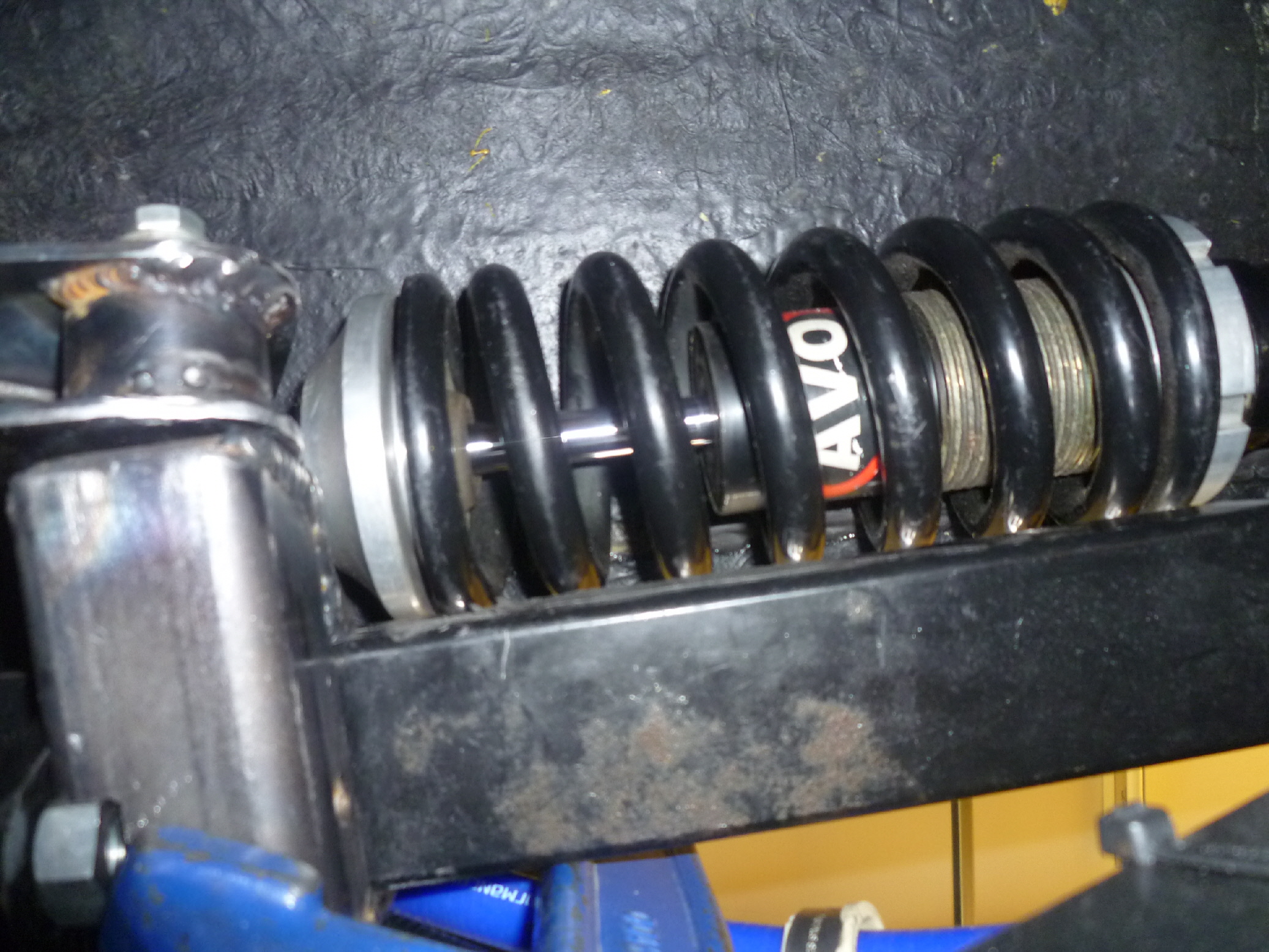
The solution was to use the space in the upper rear wing above the top chassis rail.
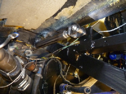
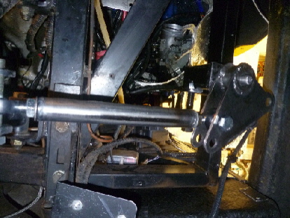
The design was to use a bell crank to transfer the upward movement of the rear suspension through 90 degrees to a damper held by a new bracket welded to the top chassis rail. The bell crank would also require a support bracket welding to the same top chassis rail.
(See photos).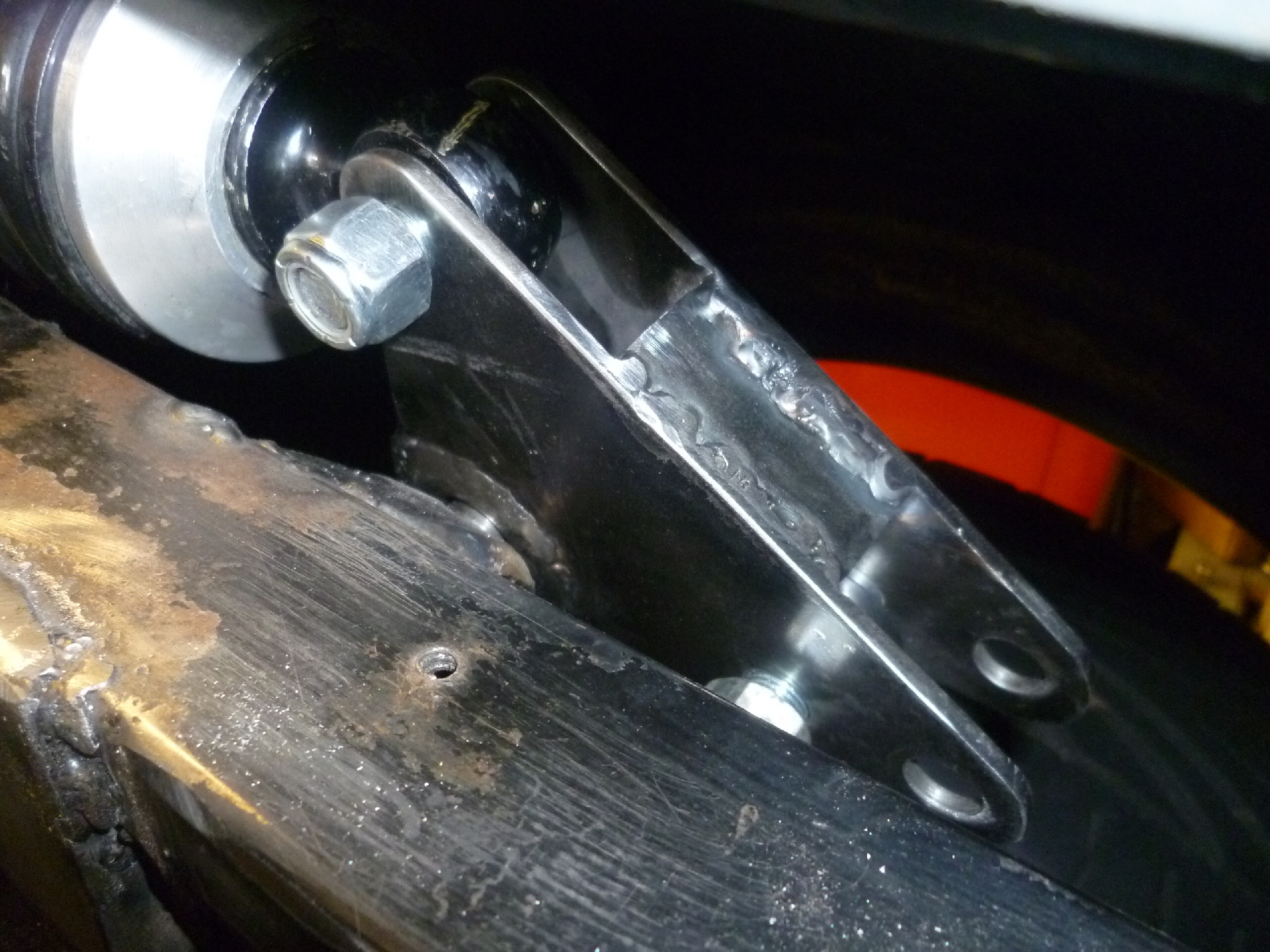
Space is quite tight so getting all the dimensions correct was important, lots of measuring; drawing plans were completed before any metal was cut. I even made a full size wooden mock up of the bell crank before ordering any metal.
Materials
4mm steel plate used for bell crank side, 36mm steel bar used to make the centre boss. Two 1 inch spherical bearing in the centre and a circlip.
Machining out the 36mm bar was very time consuming on my tiny lathe, first drilling a pilot hole through the centre followed by ½ inch drill bit.
I could now use a boring tool to remove the remaining material to achieve the 1 inch bore required for the two spherical bearing. A circlip groove was quite a challenge, having the grind a special boring tool to create the .050 inch wide slot deep enough for the circlip.
Push rod – 1 inch tube, 1/2 inch spherical rod ends one left hand thread the other right hand, and two 1/2 welded inserts.
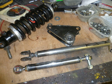
1 inch round tube cut to length, welded in ½ unf inserts both ends to take rod ends.
Brackets – 40mm square section tubing 4mm thick, 1/2 silver steel bar, 40mm wide x 4mm thick flat plate.
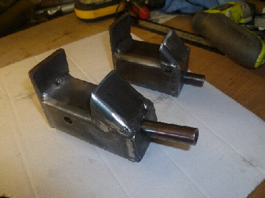
40mm Square tubing cut to length, end plate made and drilled to hold silver steel pivot. All TIG welded on the bench after checking the fit and position on chassis.
Additional supports – 1 inch round tube, fork end (made to suit) 1/2 welded inserts, 4mm flat plate.
The bell crank pivot had to be angled at 15 degrees to match the push rod coming off the existing top wishbone bracket. This was important to keep the loading thought the same plane during any suspension travel.
Early days but it seems to work, need to try different springs and push rod position to develop an improved ride both for track and road use.
Really super work Al. Very interested to hear how the new set performs on the road. Key us posted please. Michael.
Hi Michael,
Very early days, I drove the car to-day but didn’t expect any changes to ride having the same springs and ratio’s.
Need to swap springs and pushrod position and see what changes it makes.
Peter did tell me years ago to try a double spring combination of a 400 and 800 spring rate at (4 inch length each).
Could not do that running 17 inch wheels with the original set-up.
Al